You can use your RevPi base module as Modbus TCP Master to connect slaves.
You need:
- RevPi base module
- Slave
- Matching cables with RJ45 connectors
- Internet connection
Requirements:
- A web browser, e.g. Google Chrome or Mozilla Firefox.
- RevPi base module and slave devices are located in your network.
Let’s go!
- Connect the slaves to your RevPi via the RJ45 jack.
- Specify the IP address of the slaves and make a note of it. If necessary, you can find information on this in the manufacturer’s operating instructions.
- Start RevPi Status.
- Click tab SERVICES.
- Enable Modbus Master.
- Click button Save All.
You can also activate the Master function on the command line.
Enter the following command: sudo revpi-config enable pimodbus-master.
- Start PiCtory.
- In the Device Catalog, open the folder Virtual Devices.
- Select Modbus-TCP Master.

- Hold down the left mouse button and drag the Modbus TCP Master to your RevPi.
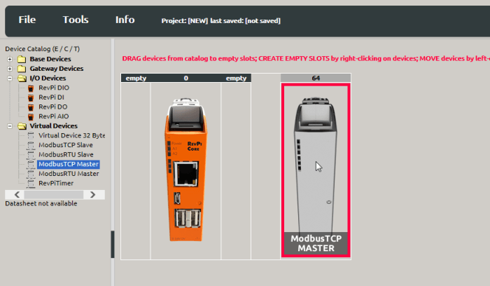
Your Modbus-TCP Master will now appear on the far right of the Configuration Board.
- Select Modbus-TCP-Master.

- Set the basic settings for your adapters in the “Device Data” window. This entry is optional. If you use a lot of devices and want to process the data later in another program, this input can be very helpful.
In the “Value Editor” we define the settings for the TCP connection. We’ve already determined the values from the sensor’s instruction manual:
| Parameter | Description |
| slave_IP_address | IP address of the Modbus TCP slave |
| slave_tcp_port | The TCP port of the Modbus TCP slave. The default value is “502”according to Modbus specification. You can change this value. This makes for instance sense if you want to implement 2 different controllers in the same network, which should not interfere with each other. |
- Right-click on the Modbus TCP Master on the Configuration Board.
- A context menu opens.
- Select the entry “Extended Data”.
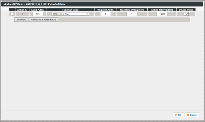
An input mask opens.
This is where you can set the Modbus commands.
| Parameter | Description |
| Unit ID | Please refer to the instruction manual of your slave, if you have to set this address. Most slaves ignore this address. In this case it is recommended to set the value 255 (invalid). |
| Function Code | Modbus has function codes that allow access to data in a certain way. We use the following function codes:
READ_COILS Reading single bits READ_DISCRETE_INPUTS Read single input bit READ_HOLDING_REGISTERS Read an whole 16-bit input/output register READ_INPUT_REGISTERS Read an whole input register (16 bits) WRITE_SINGLE_COIL Write single bit WRITE_SINGLE_REGISTER Writing a whole register WRITE_MULTIPLE_COILS Write several consecutive bits WRITE_MULTIPLE_REGISTERS Write several consecutive registers |
| Register Address | The Modbus register address or bit address of the data you want to access. You will find information on how the registers of the slave are assigned in the operating instructions of the slave. Please note the comment regarding the register address below this table! |
| Quantity of Registers | Number of registers (or bits) that are read/written |
| Action Interval | The interval at which the command is sent (in milliseconds) |
| Device Value | The variable name in the RevPi process image in which the first word or bit of the Modbus command is read or written.
Depending on the selected function code, the dropdown menu offers you the appropriate target addresses of the process image for selection. Make sure that the different commands do not overlap. |
Check how the addressing is specified at your slave.
If the slave you want to use uses 0 as the first register address, you must add a 1 to the specified value during configuration.
Example: The documentation for your slave states a register address 30053. The addresses start at 0 according to the documentation. You use address 30054 for this register when configuring a Modbus command.
- Click on „File>Save“ to save the file.
- Click on “Tools>Reset Driver”. This activates the changes for the adapter.
Do you want to continue using the settings in logiCAD3 or C?
- Click on „File>Export“.
A window opens. You can specify the format of the file and the filename.
You can choose from 2 file formats:
Export 01 creates a file that is suitable for use in logiCAD3.
Export 02 creates an offset list which you can use as basic information for your own C-program.
- Select a format you want to continue working with.
- Specify a file name.
- Click „Ok“.
Help! Error!
The Modbus master has predefined Modbus registers for status messages.
If a communication error occurs, the error code is written to the Modbus register “Modbus_Master_Status”.
The error stays in this register until the value “1” is written manually into the Modbus register “Master_Status_Reset”.
| Error code | Description |
| 0x10 | The configured device was not found.
Check if wiring is correct. |
| 0x11 | The configured device does not respond or you are using a register address which is not allowed by the slave (see note above)).
Check that the IP address is correct and that the cables are plugged in correctly. |
The Modbus master can handle up to 32 tasks. For each task there is a register for status and status reset. If an error occurs in a task, the error code is written to the Modbus register “Modbus_Action_Status_[1… 32]”.
The error stays in this register until the value “1” is written manually into the Modbus register “Action_Status_Reset_[1… 32]”.
The error codes correspond to the Modbus exception codes as specified in the Modbus specification.
The following table shows the most important error messages.
| Error code | Name | Description |
| 1 | ILLEGAL FUNCTION | The function code used is not allowed. Check if you are using the correct function code. |
| 2 | ILLEGAL DATA ADDRESS | The Modbus register address used is not valid. The register is either write-protected or invalid. Check the register address. |
| 3 | ILLEGAL DATA VALUE | At least one part of the data values used is invalid. For example, it is possible that you have entered too many registers. Check your values. |
| 13 | INVALID DATA | The slave has answered my incomplete packet. This can happen after the connection has been interrupted. Check your wiring. |
| 110 | CONNECTION TIMED OUT | The slave did not respond fast enough or not at all. Check your configuration and wiring. |
For more information on this topic, please refer to the official Modbus specifications.